Achieving a lot from your CNC router these days depend a lot on your skills and software available to you. To a large extent your software suite will determine what you can design and produce on your CNC router. A critical component of your CNC router production system is the CAM. By the end of this post you will understand what CAM software is how it works and various options for you at the moment.
What is a CAM software
CAM stands for computer aided manufacturing. It is a system for controlling production machines using numerical control(NC) codes. Gcode is the name for these NC codes. CAM softwares convert your designs into gcodes that will control motion speed direction of machine tools for the production. Most CAM softwares will allow you to view the gcodes and the toolpath generated.
Gcodes currently control various types of production machines. We will focus on CNC routers and the CAM options available. CAM softwares have ensured that hobby users and small businesses can use CNC routers in their production line. The availability of affordable CAM has drastically reduced the need for directly employing professional NC programmers saving cost for small businesses.
How a cam software works.
A CAM software is a part of CNC toolchain. Toolchain is a set of softwares that an idea goes through to arrive at the final product using a CNC router. Most items produced from a CNC router start from an idea or a picture. The CAM software will create a vector from this picture so that it can create a toolpath for the CNC router using the desired tool.
In most cases you can create your design in a Computer Aided Design(CAD) software. This CAD feature is also available in many CAM softwares. Basically you will design your idea in the CAM software if it has a CAD feature. After this is done your design is then fed into the CAM section to create operations called toolpaths for the CNC router.
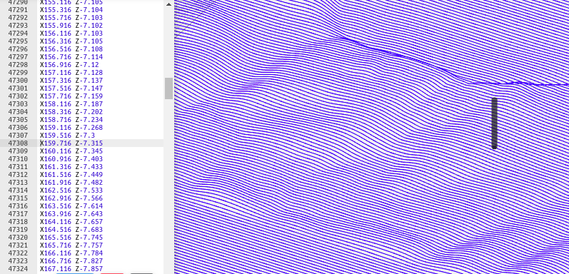
After creating the toolpath, you will have a basic visual representation of the toolpath. This allows for close inspection so you can make correction in the various parameters used in creating the toolpath. Many of the advanced softwares provide simulation of the toolpath to present an identical view of a finished operation. When the visualisation represents the design, the toolpath is then saved as a gcode file using the matching post processor for the CNC router.
Inputs required
Sometimes it is desired to just create toolpath and gcode in your CAM software. In this case a file containing already designed part produced by some CAD is required. The file should be either an image file or a vector file. Most CAM softwares accept image files and file types containing a CAD data.
When the files are coming from other CAD softwares, the most popular format for the files are DXF, SVG, DWG, EPS, OBJ, STL, 3DS. The files in dxf, svg, dog, eps format contain mainly vector designs that are two dimensional. Obj, stl, 3ds files contain three dimensional (3d) designs.
CAM softwares vary in their capabilities and features. Some of them can only handle 2 dimensional drawings and previews. Others handle 2 dimensional drawings with 3d preview, while the rest can allow you create 3d designs import and create toolpath for 3d models.
Creating gcodes in CAM softwares
In the process of generating your gcodes, you will require an input from an image or a CAD file. Varying results can be produced using these files. The required file depends on the part to produce and the available design or information.
Image files as input will enable CAM softwares produce gcodes corresponding to the image. Grayscale images are best used because the software converts the image dark and light pixels into vertical movements on z axis. Sometimes the image is first converted into vectors. This is helpful especially when creating the corresponding vector manually can be difficult and prone to error. A perfect example is the picture of a person.
CAD files containing vectors will produce toolpaths that correspond to the vectors. These vectors will often serve as boundaries for the toolpath. The CAM software will determine the vertical movement of the z axis based on the toolpath strategy. Vectors often can have profile strategy, pocket, engraving and drilling strategy assigned to it.
3D models in stl, obj formats are inputs for some CAM softwares. In most cases they will be the input for creating 3d relief objects or designs that have three dimensional features that cannot be represented by vectors. The strategy to use for them is usually raster or parrallel. This is similar to the strategy used for grayscale images and involve to and fro movement criss crossing the XY plane. While the Z axis moves up or down with respect to high or low areas of the 3d model.
CAM Software tool chain options
At the moment there are so many software tool chain option for going from design to finished piece. These CAD / CAM softwares vary greatly in features, price and acceptable operating system. We will look at some of the options available.
Open source CAM softwares.
There are some open source CAM softwares that are stable and reliable. They will find great appeal among users running opensource operating systems. Some of their features are not as richly developed as the commercial versions, but they can be used to produce amazing results.
- Inkscape – This is an opensource free vector drawing application. There is a gcodetools extension for it. This extension can be used to generate gcode for CNC routers. We may say that the gcodetools is the CAM software feature of the inkscape application. Currently inkscape comes with the gcodetools extension. It runs on Windows, Mac and Linux OS.
- PyCAM – This is a CAM software that generates gcode from CAD designs. It accepts 2d and 3d designs as input for generating gcodes. The gcode generated will work in linuxcnc controller and some other CNC controllers. PyCAM runs only on Linux.
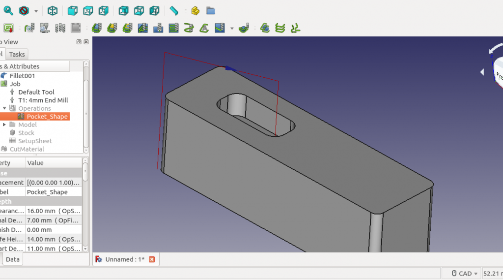
- FreeCAD – A very promising opensource CAD software. Freecad has workbenches as container for its design operations and features. One of the workbench in freecad is Path workbench. This workbench is an implementation of extensive CAM capabilities. It can be used to generate toolpath for various CNC milling operations. Its CAM can be applied to 2d and 3d designs. Freecad can run on Windows, Mac and Linux OS.
- BlenderCAM – This is a plugin for the 3d software Blender. It provides CAM functionality to Blender with a variety of toolpath strategies. BlenderCam can generate toolpaths for 2d and 3d designs. It requires some understanding of the Blender for more effective use. BlenderCAM works with Windows and Linux OS.
Commercial CAM software options
Commercial CAM options for 3 axis CNC routers are more elaborate. They range in price from few dollars to hundreds of dollars with varying capabilities and features. There is more support and documentation for the commercial CAM options.
Conclusion
You now know the steps to get the gcode for running your CNC router. The process of going from an idea to a completed part on a CNC router is clearer now. I hope you understand the general purpose and use of a CAM software for CNC routers. In future posts, we will discuss more on creating various projects on CNC routers using various strategies. Let me know how this post has helped you and what difficulties you have with your CAM or CNC.